25+ block diagram automatic control system
Different analogous systems may have same block. This is the simpler of the two systems.

Piezoelectric Sensor Pinout Working Datasheet Electronic Circuit Design Sensor Electronics Projects Diy
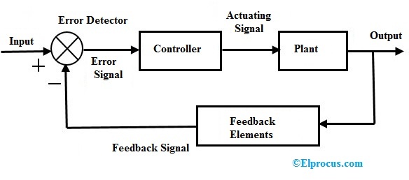
Block diagram is a pictorial representation of a control system.

. Modeling Lesson 5 Block diagrams Signal flow graphs Automatic Control by Meiling CHEN. Automatic Frequency Control Block Diagram. ȯdəmadik kəntrōl bläk dīəgram control systems A diagrammatic representation of the mathematical relationships defining the flow of.
Flight path angle is. Automatic control block summer. In control system block diagrams the energy flow is not included but as an exception this will be included in fig.
Explain the difference between an open loop and closed loop control system. Functional Software Electrical etc. It does not gives any idea about physical nature of system.
As previously we see the heart of an AFC circuit is a frequency-sensitive device such as the phase discriminator. Basic components of a control system. The open-loop system is also called the non-feedback system.
This course should provide a brief review for readers in the controlsystem engineering profession or serve as an introductory material for readers in a non-controlsystem engineering. It can be seen that the pitch attitude control system is used in Figure 24 and 25. Ad Find out why pros choose Lucidchart to make block diagrams.
A block diagram representation in which there is only one forward and feedback block along with a single summing point and take-off point is the simplest form of closed-loop control system. A graphic representation of an automatic control system in the form of a set of components into which the system may be divided according to certain. Use Lucidchart to visualize ideas make charts diagrams more.
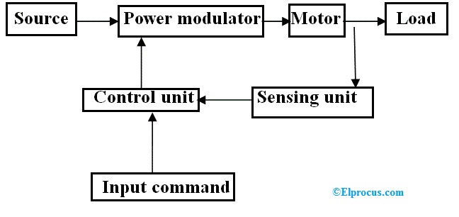
Ad Templates Tools To Make Block Diagrams. In all examples discussed above we have a similar block structure as in Figure 5. Thus the complete control action is performed by an automatic control system as shown in Figure 5.
Explain the function of an automatic control system. 17-6 to highlight in which parts of the. The block diagram of an automatic flare control system is given in Figure 24 and 25.
The blocks corresponding to 725. Identify a block diagram representation of a physical system.
Electric Drive Types Block Diagram Classification And Its Applications

Transferring Files Securely At The Foxtel Group Using Aws Transfer Family And Amazon Efs
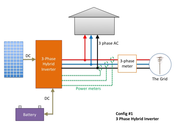
Don T Add Batteries To A 3 Phase Home Before Reading This
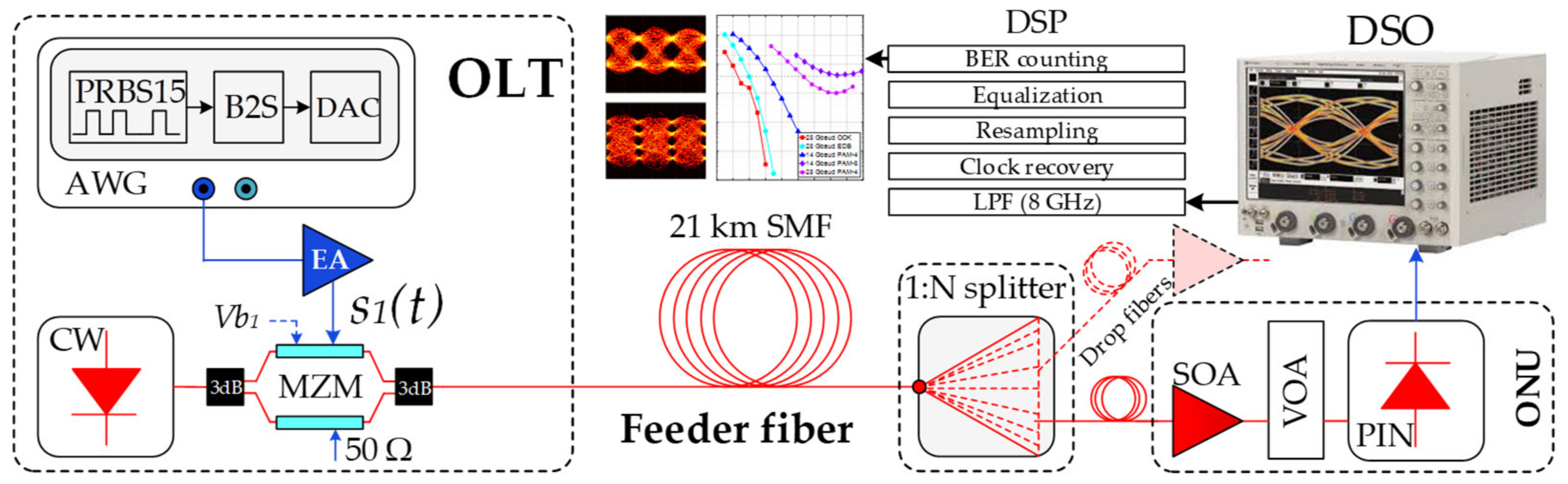
Applied Sciences Free Full Text Optical Power Budget Of 25 Gbps Im Dd Pon With Digital Signal Post Equalization Html
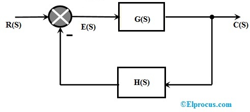
Closed Loop Control System Block Diagram Types Its Applications
What Is A Computer Block Diagram Quora
Closed Loop Control System Block Diagram Types Its Applications

Pin On Ph

Resources Archive Zuken En

The Interceptor Aims To Fix Vulnerability In Millions Of Alarm Systems

Pin On Garden
Jenkins High Availability And Disaster Recovery On Aws Aws Devops Blog

Vnr0mjaikmwzqm

Genogram A Pictorial Display Of A Person S Family Relationships Family Genogram Genogram Example Genogram Template
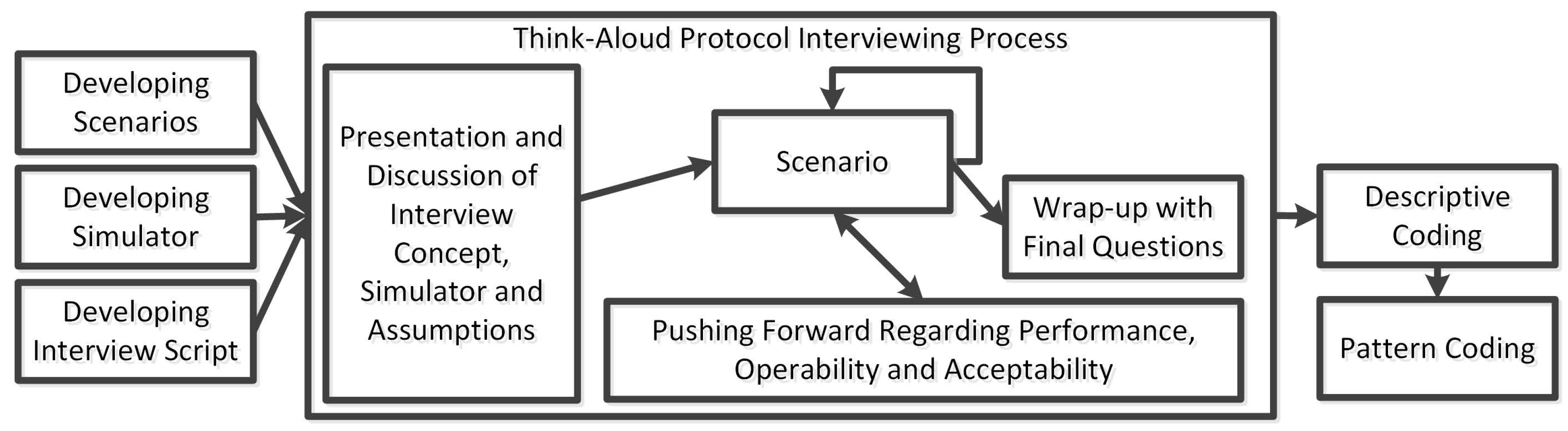
Safety Free Full Text Engineer Centred Design Factors And Methodological Approach For Maritime Autonomy Emergency Response Systems Html
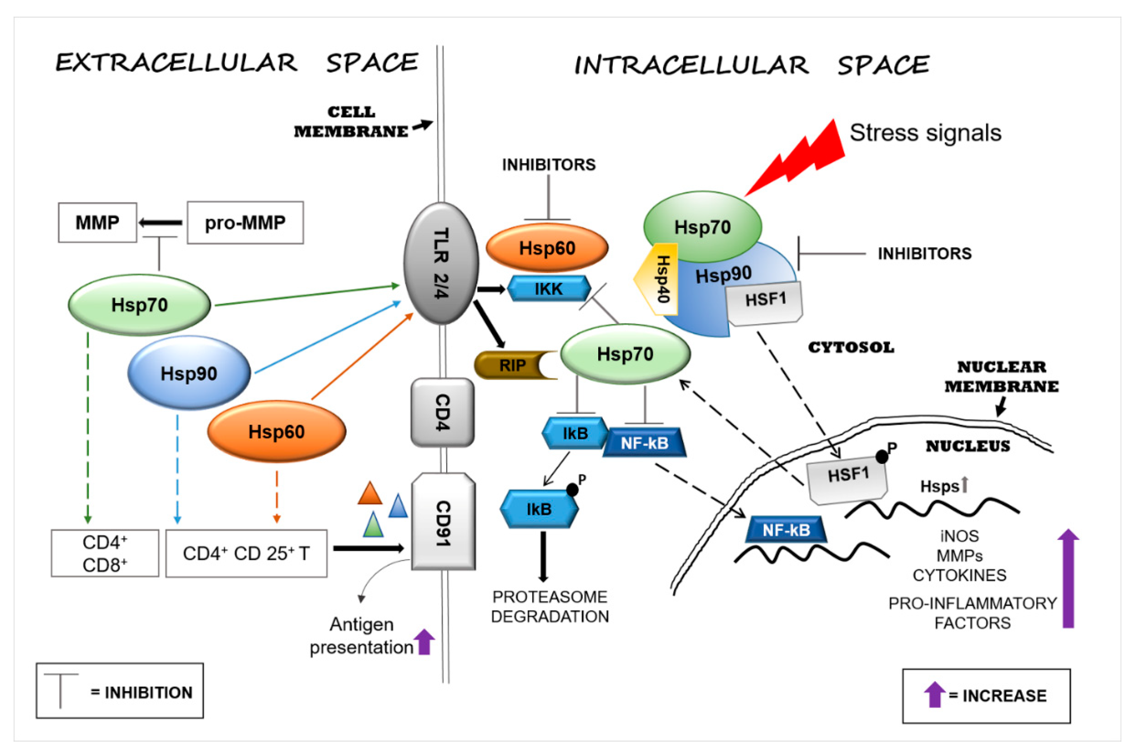
Applied Sciences Free Full Text Functions And Therapeutic Potential Of Extracellular Hsp60 Hsp70 And Hsp90 In Neuroinflammatory Disorders Html
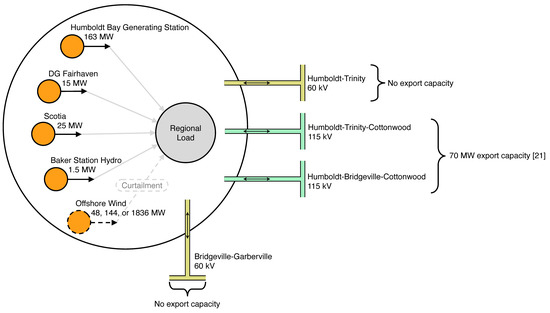
Energies Free Full Text Resource And Load Compatibility Assessment Of Wind Energy Offshore Of Humboldt County California Html